
|
81.862 bytes |
Parts Information |
Document ID: MCGN-3ZGKR3 |
Netfinity 7000 M10 - Using a serial connection to manage Remote Advanced System Management controllers or adapters
Applicable to: World-Wide
Source: Hardware Maintenance Manual
Using a Serial Connection to Manage Remote Advanced System Management Controllers or Adapters: If you want to use your system's modem to dial out and access the system management subsystem on a remote system, use Serial Connection Control to establish a connection with the remote system and then start the Advanced System Management service. You can also use Serial Connection Control to establish a null modem connection to another system. For more information on Serial Connection Control, see the Netfinity Manager User's Guide.
|
Notes |
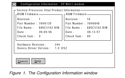
Configuration Information: The Configuration Information window (shown in Figure 1) contains detailed information about the system management subsystem, including RAM microcode, ROM microcode, and device-driver information.
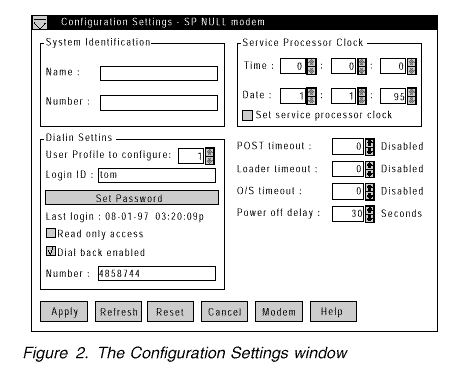
Configuration Settings: Use the selections available in the Configuration Settings window (see Figure 2 on page 50) to configure many features of the system management subsystem. These features include system identification data, dial-in security settings, the time and date reported by the system management subsystem clock, timeout and delay values, and advanced modem settings.
This window contains:
- System Identification group
- Dial-in settings group
- System Management Subsystem Clock group
- POST timeout, Loader timeout, O/S timeout, and Power off delay fields
This window also includes the Modem button. Select Modem to open the Modem Settings window (see "Modem Setting" on page 54).
The System Identification Group: The System Identification group contains two fields to help you identify the system that contains the system management subsystem.
|
Field |
Description |
|
Name |
Can be used to provide a name for the system, the name |
|
Number |
Can be used to identify the system with a specific serial |
To change the information provided by these fields:
1. In the Name or Number field, type the system information you want to record.
2. Select Apply to save this information.
The Dial-In Settings Group: Use the selections available in the Dial-In Settings group to enable or disable dial-in support, and to enable users to dial in and access the system management subsystem. The Dial-In Settings group contains the following items.
|
Item |
Description |
|
User profile to configure |
Use the spin buttons to select the user profile |
|
Login ID |
Type in this field the login ID that will be used |
|
Set Password |
A password must be provided along with the |
|
Last login |
Shows the date and time of the last successful |
|
Read only access |
If the Read only access check box is |
|
Dial back enabled |
If the Dial back enabled check box is |
|
Note |
b. In the Re-enter Password field, type the same password that you typed in the Enter Password field.
c. Click on OK to save this password and close the Set Password window.
3. Click on Apply to save the new user ID.
To delete the currently selected login ID:
1. Use the spin buttons beside the User ID to configure field to select a previously configured User profile.
2. Click on the Login ID field.
3. Using the Backspace or Delete key, delete the currently displayed login ID.
4. Click on Apply to remove the user ID.
The System Management Subsystem Clock Group: Use the selections available in the System Management Subsystem Clock group to set the time and date that is reported by the system management subsystem.
To change the currently set time or date:
1. Verify that there is a check in the Set System Management Subsystem Clock check box. This check box must be checked to enable the Advanced System Management to change the currently stored time and date values.
2. Use the spin buttons beside each field to set the time or date.
- The Time fields represent, when viewed from left to right, hours, minutes, and seconds.
- The Date fields represent, when viewed from left to right, month, date, and year.
3. Click on Apply to save the new time and date.
POST Timeout: The POST timeout field shows the number of seconds that the system management subsystem will wait for the system's power-on self-test (POST) to complete before generating a POST Timeout event. If POST takes longer than the configured amount of time to complete and the POST timeout check box (found in the Enabled Alerts Dialout group on the Automatic Dialout Settings window) is checked, the system management subsystem will automatically restart the
system one time and will attempt to forward an alert to all enabled Dialout Entries. Once the system is restarted, POST timeout is automatically disabled.
To set the POST timeout value, use the spin buttons beside the POST timeout field to set the number of seconds that the system management subsystem will wait for POST to complete. Then, click on Apply to save this value.
For more information on the Automatic Dialout Settings window, see "Automatic Dialout Settings" on page 60.
Loader Timeout: The Loader timeout field shows the number of seconds that the system management subsystem will wait for the system's loading process to complete before generating a Loader Timeout event. The Loader Timeout measures the amount of time that passes between the completion of POST and the end of operating system (O/S) startup. If this takes longer than the configured amount of time to complete and the Loader timeout check box (found in the Enabled Alerts Dialout group of the Automatic Dialout Settings window) is checked, the system management subsystem will
automatically restart the system one time and will attempt to forward an alert to all enabled Dialout Entries. Once the
system is restarted, Loader timeout is automatically disabled.
To set the Loader timeout value, use the spin buttons beside the Loader timeout field to set the number of seconds that the system management subsystem will wait between POST completion and O/S startup before generating a timeout event. Then, click on Apply to save this value.
For more information on the Automatic Dialout Settings window, see "Automatic Dialout Settings" on page 60.
O/S Timeout: A periodic signal is sent from the Netfinity Advanced System Management PCI Adapter to the O/S to confirm that the O/S is running properly. The O/S Timeout event occurs when the O/S the Netfinity Advanced System Management PCI Adapter performs its automatic dialout functions if there is no response to the signal; that is, if the O/S Timeout pulse is not detected.
The O/S timeout field shows the number of seconds that the system management subsystem will wait for the system's operating system to respond before generating an O/S Timeout event. If the O/S takes longer than the configured amount of time to respond and the device driver is installed and running correctly, the system management subsystem will attempt to restart the system, and if the O/S timeout check box (found in the Enabled Alerts Dialout group of the Automatic Dialout Settings window) is checked, the system management subsystem will automatically restart the system one time and will attempt to forward an alert to all enabled Dialout Entries.
To set the O/S timeout value, use the spin buttons beside the O/S timeout field to set the number of seconds that the system management subsystem will wait for the system's operating system to respond before generating an O/S Timeout event. Then, click on Apply to save this value.
For more information on the Automatic Dialout Settings window, see "Automatic Dialout Settings" on page 60.
Power Off Delay: The Power off delay field shows the number of seconds that the system management subsystem will wait for the system's operating system shutdown process to complete before powering off the system.
When the system management subsystem initiates a power down procedure and the Power off check box (found in the Enabled Alerts Dialout group of the Automatic Dialout Settings window) is checked, the system management subsystem will automatically attempt to forward an alert to all enabled Dialout Entries. This alert is forwarded after the system is powered off and the Power off delay time has passed.
To set the power off delay value, use the spin buttons beside the Power off delay field to set the number of seconds that the system management subsystem will wait for the system's operating system shutdown to complete before powering off the system. Then, click on Apply to save this value.
For more information on the Automatic Dialout Settings window, see "Automatic Dialout Settings" on page 60.
Other Configuration Settings Functions: The Configurations Settings window also includes three additional buttons:
|
Button |
Description |
|
Refresh |
Select Refresh to update all data that is shown on the |
|
Reset |
Select Reset to set all Advanced System Management |
|
Cancel |
Select Cancel to close this window without saving any |
|
Search Keywords |
| |
|
Document Category |
Advanced Systems Management | |
|
Date Created |
21-10-98 | |
|
Last Updated |
18-01-99 | |
|
Revision Date |
18-01-2000 | |
|
Brand |
IBM PC Server | |
|
Product Family |
Netfinity 7000 M10 | |
|
Machine Type |
8680 | |
|
Model |
all | |
|
TypeModel |
| |
|
Retain Tip (if applicable) |
| |
|
Reverse Doclinks |