

|
79.625 bytes |
Service Hints & Tips |
Document ID: DDSE-3QNJES |
PCServer704 - Processor Board Information
Applicable to: World-Wide
Processor Boards
1st Processor Board
Note
The 1st processor board (primary connectors) must be installed with the component-side down.
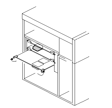
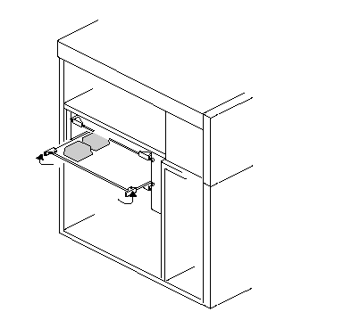
2nd Processor Board
Note
The 2nd processor board (secondary connectors) must be installed with the component-side up.
Jumpers
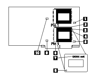
1. J102, (reserved)
2. Processor Lever
3. Processor socket
4. Processor chip
5. J107, (reserved)
6. Pin-1 on processor chip
7. Processor identification
8. Pin-1 on processor socket
9. J106, (reserved)
10. J101, (reserved)
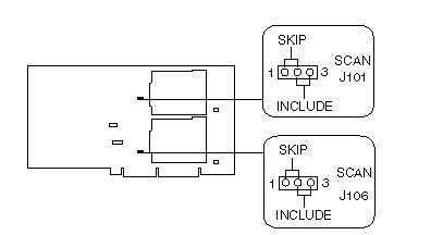
SCAN Jumpers (J101 and J106)
|
Jumper Pins Description |
|
J101 and J106, 1-2 Processor not installed in adjacent SCAN 2-3 processor installed in adjacent slot Factory default setting |
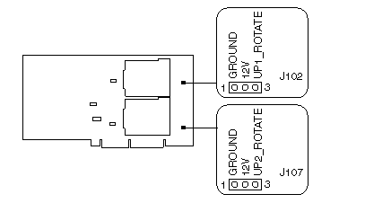
Fan Sink Jumpers (J102 and J107)
|
Jumper Pins Description |
|
J102 and J107, 1-2 Provides power to fan sink Factory default setting |
VID Jumper (J103)

|
Jumper Pins Description |
|
J103,Voltage 1-2 Reserved Factory default setting |
Frequency Select Jumper (J105)

|
Frequency Pins Pins Pins |
|
150/60MHz No No No 180/60MHz No No Jumper 210/60MHz No Jumper No
166/66MHz1 Jumper No No 200/66MHz Jumper No Jumper |
|
Search Keywords |
| |
|
Hint Category |
Hardware Maintenance Information, Processors | |
|
Date Created |
14-06-96 | |
|
Last Updated |
22-01-99 | |
|
Revision Date |
30-05-99 | |
|
Brand |
IBM PC Server | |
|
Product Family |
PC Server 704 | |
|
Machine Type |
8650 | |
|
Model |
| |
|
TypeModel |
| |
|
Retain Tip (if applicable) |
| |
|
Reverse Doclinks |