This chapter describes the basic concepts related to the display of image data by the graPHIGS API
An image is defined by an image board, which is a two-dimensional (2D) array of data values treated as a resource of the graPHIGS API nucleus. Note that an image board is not a physical piece of hardware, but a conceptual place to store image data. An image can be displayed on the workstation by mapping a defined image to a workstation view.
In the most general sense, an image is a mapping function from a 2D surface into a color space. To represent the function in a digital form, the image is sampled both within its definition domain and value domain. We assume that the definition domain is a planar rectangle and the function is sampled at grid points with regular intervals. Therefore, the image is represented by a 2D array of color values.
Color values can be represented by a vector within a normalized three-dimensional color space, so the image can be represented by a two-dimensional array of three-dimensional vectors. However, such a representation requires a large amount of storage when each color value is represented by a triplet of real values. To reduce the amount of data, color values are quantized. Two quantization methods are commonly used in many image applications.
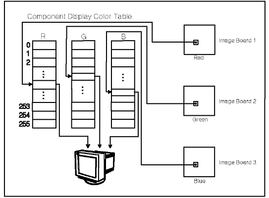
One method is to quantize three color primaries independently and is called scalar quantization, as shown in the figure, "Scalar Quantization." The normal RGB representation of images is a typical example of this method. Each pixel is represented by three indexes each of which specifies one representative value of a color component. Note that the quantizations of three primaries need not be equal interval sampling (for example, r-corrected RGB) nor to be identical depth (for example, the broadcast TV color system, digital YIQ, with different bit length).
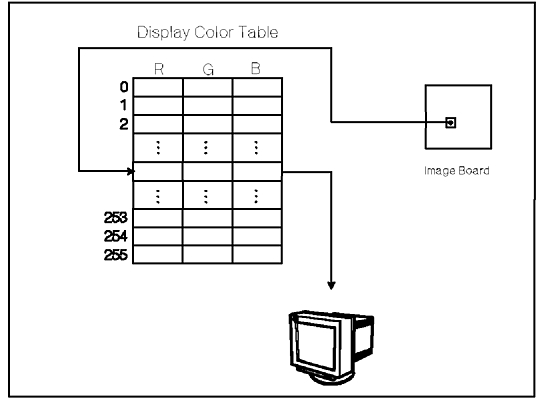
Another method is to quantize color values as three-dimensional vectors and is called vector quantization, as shown in the figure, "Vector Quantization." An image handled by the Pixel (GPPXL2 and GPPXL3) subroutines of the API is a typical example of this method. Each pixel is represented by an index specifying one representative color selected from a three-dimensional color space. Note that this method of quantization includes binary and grey scale images as special cases in which the color representatives are selected from monochrome colors.
Notice that in both cases, an image is represented by a 2D array of color table indexes. The only difference between them is the connection between the array and color table. In the scalar quantized image, the color table is indexed by three indexes separately for each color component but in the vector quantized image, it is indexed as a whole by a single index.
Defining, manipulating and displaying an image is similar to that of geometric objects. In addition, the display of an image merges into the rendering pipeline of geometric objects, resulting in both the image and geometric data showing on the display surface. You may display an image using of the following graPHIGS API facilities:
To store the 2D arrays of indexes described above, the graPHIGS API supports a nucleus resource called an image board Each pixel is referred to by two indexes where the pixel at the lower-left corner has an index pair (0,0). Pixels at the lower-right, top-left and top-right corner are referred to by index pairs (SX-1,0), (0,SY-1) and (SX-1,SY-1), respectively, where SX and SY are the horizontal and vertical size of the image board.
Conceptually, the image board is an abstraction of a frame buffer for raster type displays. However, image boards are not necessarily realized by special memory such as a physical frame buffer. A nucleus implementation can utilize any storage for an image board and your application can create and delete image boards independent of the physical frame buffer.
An image board is created using the Create Image Board (GPCRIB) subroutine. GPCRIB takes the following parameters:
The bit depth parameter must be one of those supported on the target nucleus. The graPHIGS API generally supports bit depth of 1,2,4,8 and 12, but the application should inquire the actual list of bit depths available on a given nucleus using the Inquire Image Board Facilities (GPQIBF) subroutine.
The conceptual size of the image board is determined by three size parameters, bit length of each pixel, and the horizontal and vertical dimensions of the image board array. However, the actual amount of storage used for an image board may differ between nucleus implementations because of the differences in their storage organization. A nucleus implementation can use any storage mechanism (for example, it can use any compressed format) to realize image boards.
You can attach an image board created by another application process to your application using the Attach Resource (GPATR) subroutine with the following parameters:
As for other nucleus resources like structure stores or workstations, the resource identifier of the image board and its password is known only to the application process which created the image board. Therefore, your application process which uses the Attach Resource (GPATR) subroutine, for an image board, must get the information from the application process which created the image board.
An image board is detached from the shell using the Detach Resource (GPDTR) subroutine which takes with an image board identifier as a parameter.
The graPHIGS API provides functions that enable you to manipulate image board data content.
The Fill Rectangle (GPFRCT) subroutine is used to fill a portion of an image board with a constant value. Note that the contents of an image board are undefined when the image board is created. If the application wants to initialize all pixels of the image board to a constant value (clear the image board), the application must explicitly fill the entire image board with the value by using this subroutine.
Write Rectangle (GPWRCT) and Read Rectangle (GPRRCT) subroutines are used to move image data to and from an image board. Both subroutines take the following parameters:
The graPHIGS API supports one type of image format: the pixel array. This type of image format description requires the following information:
The table below lists the minimum and recommended
horizontal size based on the image format depth.
| Bit Depth | Required Minimum Horizontal Size |
Recommended Horizontal Size |
|---|---|---|
| 1 | Multiple of 8 | Multiple of 32 |
| 2 | Multiple of 4 | Multiple of 16 |
| 4 | Multiple of 2 | Multiple of 8 |
| 8 | No Restriction | Multiple of 4 |
| 16 | No Restriction | Multiple of 2 |
Your application can also transfer image data from one image board to another using the Transfer Rectangle (GPTRCT) subroutine.
In addition, your application can perform operations on one or two image boards and place the result into another image board using the following two subroutines:
GPTWPO processes a rectangular area of the source image board and places the result into another rectangular area of the target image board. The operation type parameter specifies the process to be performed on the source rectangle. The following operation is defined:
GPTHPO performs a binary operation on the two source image boards and stores the result into the target image board. The following two operations are currently defined:
Image boards which are the target of this subroutine call must reside on the same nucleus and the actually supported pixel operations may depend on the nucleus where these image boards reside. Your application can inquire a list of operations supported by a given nucleus with the Inquire Available Pixel Operations (GPQPO) subroutine.
All source and target rectangles must always have the same horizontal and vertical size and be entirely within the source image data. If the target rectangle is not entirely within the target image data, pixels falling outside of the target are discarded. Also, the bit lengths of the image boards need not be the same. When the bit length of the target pixel is less than that of the source, the source bit string is truncated by discarding the most significant part. When the bit length of the target pixel is larger than that of the source, the source bit string is expanded by adding 0-bits to the most significant part. Note too, that the target image board for GPTRCT, GPTWPO, and GPTHPO can be the same functions as the source rectangles.
To display the contents of an image board, your application must call the Define Image (GPDFI) subroutine with the following parameters:
An image definition is stored in the specified entry of the workstation's image table. Each workstation has an image table with a predefined number of entries and all entries are initialized as undefined when the workstation is opened.
The image connection type specifies the relationship ("connection") between the image board contents and the color table. This defines the colors of pixels. (These colors are then quantized and written to the frame buffer.) There are 3 types of connections supported:
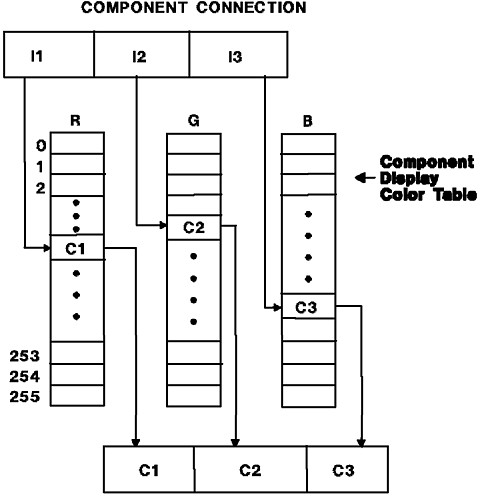
The component connection is used for scalar color quantization. Three image board identifiers are specified. To obtain a pixel color, three indices are used, one from each of the three image boards at the same pixel location. The three indices are used independently to select a color component from the specified color table. The first index selects the first color component, the second index selects the second color component, and the third index selects the third color component. The resulting color value is the color of the pixel, as shown in the figure, "Component Image Board Connection."
The indexed connection is used for vector color quantization. One image board identifier is specified. A pixel color is obtained by using the index at the pixel location. The index is used to select the three color components from the specified color table. The color value obtained is the color of the pixel.
The frame-buffer-compatible connection is used for a color connection that uses the workstation's color facilities. The number of image board identifiers specified is the same as the number of frame buffer components of the workstation. (Obtain this value using the Inquire Frame Buffer Characteristics (GPQFBC) subroutine.) In addition, the color table used will always be the default color table. If the frame buffer has 1 component, then frame-buffer-compatible is similar to an indexed connection using the default color table. If the frame buffer has 3 components, then frame-buffer-compatible is similar to a component connection using the default color table.
The actual meaning of the Frame Buffer Compatible connection type is that operations on the image data are performed in pixel space, not in a color space. In many cases, this will be the preferred connection type for workstations with a component frame buffer since the pixels values themselves can be treated as a color space. No additional color mapping is necessary.
An entry of the image table becomes undefined when the Cancel Image (GPCAI) subroutine is called with a specified image index.
Your application can inquire the image capabilities of a workstation and the current status of an image definition using the subroutines:
Your application can create color tables that are used during the image color processing using the Create Color Table (GPCRC) subroutine. These image color tables are identified by a color table identifier, which must be a positive integer. (A workstation has two color tables: a DISPLAY color table, whose color table identifier is the value -1 and a RENDERING color table, whose color table identifier is the value 0.) The Set Extended Color Representation (GPXCR) subroutine sets the image color table entries. When using a COMPONENT or INDEXED image connection type, you must pass the color table identifier of the image color table to be used to obtain the color value of each pixel.
To delete an image color table, use the the Delete Color Table (GPDLC) subroutine, which takes an image color table identifier as a parameter. If an image is currently defined on the workstation using this color table, then the image is undefined (cancelled), before the color table is deleted.
You can display any defined image by mapping a rectangular part of the image onto a parallelogram in the World Coordinates (WC) using the following subroutines:
The parallelogram in the WC space onto which the image rectangle is mapped is defined as follows. Let P, Q, and R be three points specified throughout either GPCIM2 or GPCIM3 The parallelogram has its four vertices on P,Q,R and Q+(R-P). Image data within the image rectangle is mapped to this parallelogram such that the bottom-left corner is on P, bottom-right corner is on Q and top-left corner is on R.
The actual appearance of an image when it is displayed on a display surface is controlled by the mapping type parameter of GPCIM2 and GPCIM3 Currently only one mapping type, PIXEL_BY_PIXEL , is defined. In PIXEL_BY_PIXEL mapping, only the first point P the image mapping is transformed by the viewing transformation and workstation transformation. Pixel data within the image rectangle is displayed without any transformation. The view clip and workstation clip may be applied to the image in a workstation-dependent way. This display method corresponds to the pixel primitives supported by the graPHIGS API
Although images are mapped in 3D World Coordinates as are graphical primitives, images are not treated as graphical entities. All images within a view are always rendered as a background picture of the view and no hidden line or hidden surface process (HLHSR) is applied to the images. The priority parameter of GPCIM2 and GPCIM3 controls only the priorities of images and has no relation to those of graphical root structures. Also, image data is not pick detectable. An image mapping can be performed in a view in PARALLEL projection only. If the view is in PERSPECTIVE projection, an error is generated. If a PARALLEL projection is changed to PERSPECTIVE projection, then the image mapping is deleted.
When GPCIM2 or GPCIM3 is applied to an already existing image mapping, it is treated as a modification of the image mapping parameters. When an image definition which is already used for any image mapping is re-defined, the newly defined image is displayed at the next update.
An image mapping is deleted from the view by the Delete Image Mapping (GPDIM) subroutine or when the image definition referred to by the image mapping becomes undefined. Any modification of the image definition other than cancelling the image, does not affect any image mappings. Such modification will be visualized at the next update.
Inquire the workstation capabilities related to the image mapping and current status of the image mapping using the following graPHIGS API subroutines: