its graphical data into structures. In some cases, where the complexity of the drawing or application demands it, the structures can be linked together in a hierarchical type of network.
Although structures can be useful for organizing the graphical data, they are not required in order to display a picture. Graphical data can be sent directly to a workstation for display without storing the data in structures. See Chapter 14. "Explicit Traversal Control" for a description of this processing.
Your application uses structures to establish relationships between the basic elements of your graphics data. This relationship is based on a hierarchical network, which enables structures to reference or execute other structures. Once a structure has been created, it can easily be modified by inserting or deleting structure elements.
All structures are defined in a structure store. At the time your application issued the Open graPHIGS subroutine, a structure store was created and selected as the current structure store. All structures created after this subroutine call will be defined in this structure store.
In the Sample Program, you created the following structure to draw the house:
       CALL GPOPST(STRID(1))
       CALL GPPL2(6,2, HOUSE)
       CALL GPCLST
Each data item within the structure is called a structure element The sample program structure has only one element, called an output primitive, which allows you to draw the house. Structure elements vary greatly in their content and organization, enabling your application to define, organize, and control all parts of a graphical model. The following is a list of element types that may be contained in a structure:
| Sample Program |
|---|
Now, refer back to the sample program and modify it according to the following statements:
|
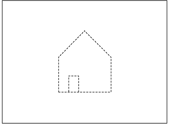
Recompile, load and run the program after you have input these modifications. The figure, "Modified Sample Program Picture," shows the picture you will get when the modified sample program is executed.
As you can see, some new elements have been added to the structure. The line type and position of the house have been modified. One structure element modified the line type attribute setting of the output primitive and another applied a modeling transformation to it. In the chapters that follow, you will learn in more detail how to define each structure element. In the previous structure you were using default values. Information on default settings can be found in The graPHIGS Programming Interface: Technical Reference
If your application needs to create a structure or access the content of an existing structure, it issues an Open Structure (GPOPST) subroutine. Your application can assign each structure a unique structure identifier to aid in the differentiation between structures. To open an existing structure, your application specifies the existing structure's identifier in the GPOPST subroutine.
When your application tries to open a non-existent structure by specifying an unused structure identifier, the API creates a new empty structure. Other ways in which the system implicitly creates a structure are:
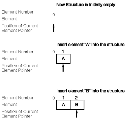
When a structure is open, it has a conceptual current element pointer The element pointer is a mechanism that lets your application locate a position within the open structure.
When an application program opens a structure, the element pointer points to the end of the structure. In an empty structure, the element pointer points to the conceptual element zero, which is null.
As elements are added, the system increments the element pointer to the most recently added element. The system also assigns a sequence number to each element. The first element is always 1, the second is always 2, and so on. The figure, "Inserting Elements Into an Empty Structure," shows how your application adds elements to a structure, and how the system increments the current element pointer.
As previously discussed, the graPHIGS API gives your application the ability to group graphic elements within structures. It also enables your application to organize structures into hierarchical structure networks.
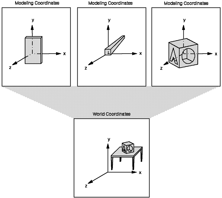
In many instances, a hierarchy can effectively represent the relationships among the parts of a model. This capability provides a way for your application to functionally attach (assemble) individually defined primitives. For example, your application can functionally attach a table's legs to its top. The figure, "Using Modeling Transformations to Assemble Graphics Models," shows the assembly of a graphics model from individually defined primitives.
In order to establish hierarchies, the graPHIGS API provides a structure element that invokes other structures. To create a structure element that invokes another structure, use the Execute Structure (GPEXST) subroutine.
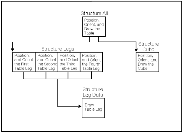
One way to organize the table's graphics data is to imbed a structure reference in the tabletop structure that invokes the leg's structure. The figure, "Hierarchical Structure Relationships," depicts one of many ways to organize the table's top and legs hierarchically.
Note: The depicted organization is only intended to illustrate hierarchies. Other structure organizations may perform better in such cases.
Hierarchically organized structures also provide efficient use of storage. Your application needs to define common parts only once, then reference them as many times as necessary. Rather than defining duplicate leg structures, your application invokes the same leg structure many times.
The boxes shown in the figure, "Hierarchical Structure Relationships," represent structures. Their organization enables your application to define the position of each leg relative to the tabletop's position. If your application repositions the top, the legs inherit that new position. The attached legs are automatically repositioned relative to the new position of the top.
At this point, you are ready to modify the sample program and create another structure. This new structure will add a door to the house.
| Sample Program |
|---|
Modify your house sample program according to the following statements to create a new structure.
|
Now run the sample program. Note that although no line type was specified for the door, it is also a dashed line. Being a child structure of structure 1, the door has inherited its linetype attribute. To assemble the door with the house your application program makes use of modeling transformation (TRANSD ) which moves the door to the correct position within the house drawing. The house modeling transformation (matrix) is also inherited by the door and allows it to move with the house to the center of the screen. See the figure, "Modified Sample Program Output."
Hierarchies impose the passing of attributes from parent to child structure. If there was another child structure which drew a polyline, it would inherit the style and color attributes of its parent structure, in this case structure 1.
The ability to inherit attributes and transformations reduces the need for editing every related structure in a complex model. It also enables your application to easily alter the relationships among models and between parts of models.
Since there are many ways to establish hierarchical structure networks, the actual organization depends on the needs of your application.
Operations on the currently opened structure end when your application closes the structure with the Close Structure (GPCLST) subroutine.
The graPHIGS API provides operations that affect entire structures, and permit your application to inquire and modify the content of structures. Those topics are discussed in Chapter 8. "Structure Editing"