System Upgrades: Dell Latitude C840
Service Manual
Back to Contents Page
Dell™ Latitude™ C840
Service Manual
Memory Modules
Modem Daughter Card
Mini PCI Card
NOTICE: Disconnect the computer and any attached devices from electrical
outlets and remove any installed batteries.
NOTICE: To avoid ESD, ground yourself by using a wrist grounding strap or
by periodically touching unpainted metal on the computer.
Preparing to Work Inside the Computer ."
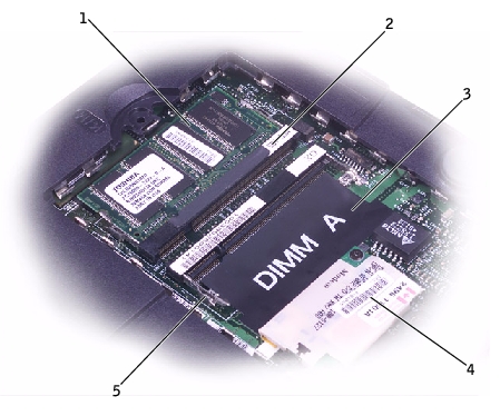
1
DIMM B
2
memory module sockets (2)
3
DIMM A socket
4
modem daughter card
5
metal tabs (2 per socket)
memory module/modem cover .
NOTE: Memory modules are keyed to fit into their sockets in only one
direction.
NOTICE: Disconnect the computer and any attached devices from electrical
outlets and remove any installed batteries.
NOTICE: To avoid ESD, ground yourself by using a wrist grounding strap or
by periodically touching unpainted metal on the computer.
Preparing to Work Inside the Computer ."
memory module/modem
cover .
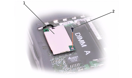
1
modem daughter card
2
M2 x 3-mm screw
NOTICE: Do not pull on the modem cable. Pull the connector on the end of
the cable to disconnect the cable.
NOTICE: The cable connectors are keyed for correct insertion. Do not force
the connections.
You must remove the optional Mini PCI wireless modem (if installed) before the system board can be removed. A wireless modem card must be connected to the internal antenna of the computer.
NOTICE: Disconnect the computer and attached devices from electrical
outlets and remove any installed batteries.
NOTICE: To avoid ESD, ground yourself by using a wrist grounding strap or
by periodically touching unpainted metal on the computer.
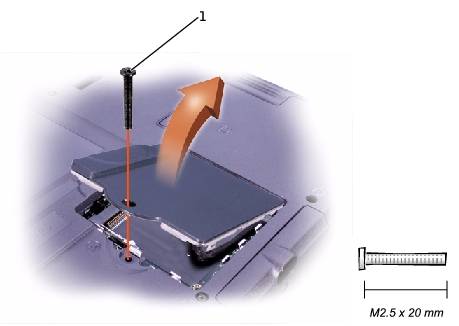
Mini PCI Card Cover
Preparing to Work Inside the Computer ."
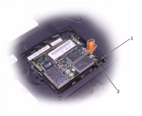
NOTICE: The connectors are keyed for correct insertion; do not force the
connections.
1
internal-antenna cable
2
primary-antenna connector on card
Back to Contents Page
 Memory Modules