
|
44.201 bytes |
Service Hints & Tips |
Document ID: LWIK-3SQN3Z |
TP 600/E - FRU Removals and Replacements
Applicable to: World-Wide
The following information is intended for IBM Dealers and Authorized Servicers only. Customers attempting to follow any of the procedures below may void their warranty.
FRU Removals and Replacements
This section contains information about removals and replacements.
o Do not damage any parts. Only certified and trained personnel should service the computer.
o The arrows in the Removals and Replacements section show the direction of movement to remove a FRU, or to turn a screw to release the FRU. The arrows are marked in numeric order, in square callouts, to show the correct sequence of removal.
o When other FRUs must be removed before the failing FRU is removed, they are listed at the top of the page.
o To replace a FRU, reverse the removal procedure and follow any notes that pertain to replacement.
See Locations for internal cable connections and arrangement information.
o When replacing a FRU, use the correct screw size as shown in the procedures.
|
Safety Notice 1: Translation on page 3 |
|
Safety Notice 4: Translation on page 6 |
|
Safety Notice 8: Translation on page 9 |
An electrostatic discharge (ESD) strap (P/N 6405959) must be used to establish personal grounding.
FRU Service Procedures
Review the following procedures before replacing any FRU.
LCD FRU Replacement Notice: The TFT LCD for the notebook computer contains over 2,359,296 thin-film transistors (TFTs). A small number of missing, discolored, or lighted dots (on all the time) is characteristic of TFT LCD technology, but excessive pixel problems can cause viewing concerns. The LCD should be replaced if the number of missing, discolored, or lighted dots in any background is 21 or more.
Replacing the System Board: The EEPROM on the system board contains the vital product data (VPD) that is, a system unit serial number and a system board serial number. When you replace the system board, restore the system unit serial number using the Set system identification utility in the ThinkPad hardware maintenance diskette. The serial number label is attached to the computer.
Note: Do not power off the computer while restoring the VPD.
Important Notice
This computer uses special nylon-coated screws with the following characteristics:
o They maintain tight connections.
o They do not easily come loose, even with shock or vibration.
o They need additional force to tighten.
o They should be used only once.
Do the following when you service this machine:
o Have a screw kit (FRU 05K4841) available.
o Always use new screws if you are instructed.
o Use a torque screwdriver if you have one.
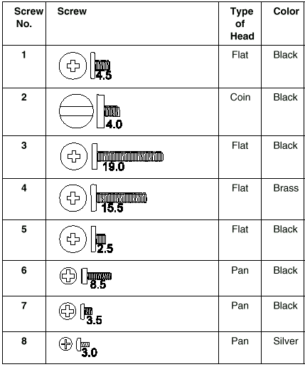
Screw Information: The following types of screws are used in this machine. Use the correct screw in the Screw Kit (FRU 05K4841) when you replacing any FRUs. There is no number-2 screw in this kit. The number under the screw shows the length of the thread of a screw in mm.

 - 1010 Backup battery
 - 1020 DIMM
 - 1030 Battery pack
 - 1040 Hard drive
 - 1050 UlraslimBay Device
 - 1060 Keyboard assembly
 - 1070 Keyboard
 - 1080 Speakers
 - 1085 Speaker cable
 - 1090 LCD assembly
 - 1100 PC Card assembly
 - 1110 Modem card
 - 1120 Sub card
 - 1130 CPU card and fan
 - 1140 Guide rail, microphone cable and TV out card
 - 1150 System board
 - 2010 LCD front cover
 - 2020 LCD hinges and cables
 - 2030 Inverter card
|
Search Keywords |
| |
|
Hint Category |
Hardware Maintenance Information | |
|
Date Created |
19-03-98 | |
|
Last Updated |
19-01-99 | |
|
Revision Date |
19-01-2000 | |
|
Brand |
IBM ThinkPad | |
|
Product Family |
ThinkPad 600, ThinkPad 600E | |
|
Machine Type |
2645, 2646 | |
|
Model |
Various | |
|
TypeModel |
| |
|
Retain Tip (if applicable) |
| |
|
Reverse Doclinks |