 Display Assembly
Dell™ Inspiron™ 1100 and 5100 Service Manual

|
CAUTION: Before performing the following procedures, read the safety instructions in your Owner's Manual. |
|
|
CAUTION: To prevent static damage to components inside your computer, discharge static electricity from your body before you touch any of your computer's electronic components. You can do so by touching an unpainted metal surface. |
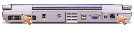

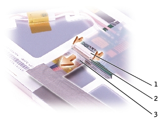
1 |
|
2 |
|
3 |
|
4 |
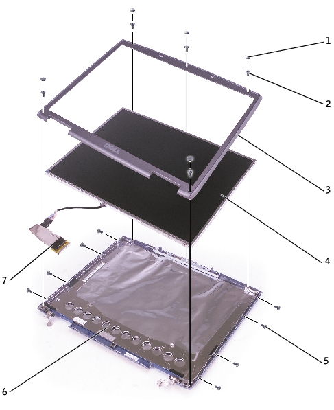
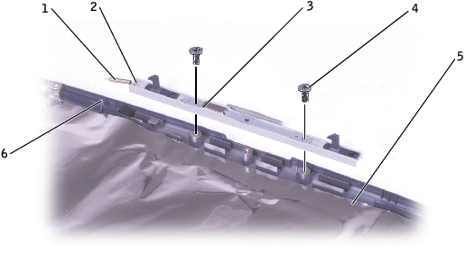
1 |
|
2 |
|
3 |
|
4 |
|
5 |
|
6 |
|
7 |
|
|
CAUTION: Before performing the following procedures, read the safety instructions in your Owner's Manual. |
|
|
CAUTION: To prevent static damage to components inside your computer, discharge static electricity from your body before you touch any of your computer's electronic components. You can do so by touching an unpainted metal surface. |
 |
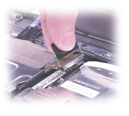
NOTICE: Carefully separate the bezel from the top cover to avoid damage to the bezel. |
|
|
CAUTION: Before performing the following procedures, read the safety instructions in your Owner's Manual. |
|
|
CAUTION: To prevent static damage to components inside your computer, discharge static electricity from your body before you touch any of your computer's electronic components. You can do so by touching an unpainted metal surface. |
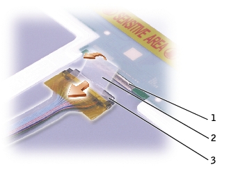
1 |
|
2 |
|
3 |
1 |
|
2 |
|
3 |
|
|
CAUTION: Before performing the following procedures, read the safety instructions in your Owner's Manual. |
|
|
CAUTION: To prevent static damage to components inside your computer, discharge static electricity from your body before you touch any of your computer's electronic components. You can do so by touching an unpainted metal surface. |
1 |
|
2 |
|
3 |
|
4 |
|
5 |
|
6 |